Generic Annotations in Revit
I have been working on a Revit implementation and just discovered by accident that you can include dimension parameters that behave like reporting parameters in the labels of Generic Annotations. While very intrigued, I have not come up with a really practical use of this yet.
For those of you not familiar, let me take a few moments to explain Generic Annotations. For the AutoCAD users, a Generic Annotation Symbol in Revit is basically a block with attributes from AutoCAD. In other words, it is a simple symbol with user editable text field(s). The nice thing about these is that the text fields can receive basically any input you like and you can even schedule all the values in a “Note Block” schedule. For the BIM purists, Generic Annotations are NOT very “smart.” This is because the data is not being reported from the model like a normal tag, rather the data lives in the fields of the Generic Annotation object itself. However, smart or not, they have their uses and in some cases can be just what you need in your documentation efforts.
There are some unfortunate terminology hurdles to overcome when using them however:
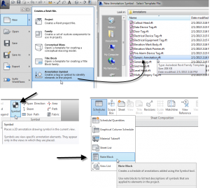
- To create a new Generic Annotation family, use the Generic Annotation.rte family template. (Application menu>New>Annotation Symbol). Do not change the category.
- To place a Generic Annotation family in your project, use the Symbol tool. (Annotate tab > Symbol panel > Symbol tool).
- To schedule the values you input in the fields, create a Note Block schedule. (View tab > Create panel > Schedules drop down > Note Block).
Got it? The family is a Generic Annotation, the tool is Symbol and the schedule is Note Block. Weird.
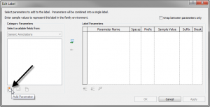
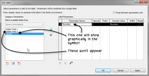
When creating the Generic Annotation, if you want to have fields, add a Label like you would in any annotation family. When you do, the list will appear empty. This is because we left the category set to Generic Annotations. This is what we want. At the bottom left corner of the dialog, you can add custom parameters to the symbol. These will become the fields that we can edit. Click the Add Parameter icon, configure the parameter as you like, usually a Text parameter so that you can type in anything you want. However, in some cases you may want Number or Integer. Add it to the label. You can add as many as you like.
A really interesting tidbit here. You can add several additional parameters beyond what you need to appear in the symbol. In other words, you can add “hidden” fields. Any parameters that you add but do not include in the label on the right will still be able to receive values in the project and more importantly, will still appear in the Note Block schedule! Just add the parameters, but do not put them in the label at the right. When you OK out of the dialog, you can add some graphics like a circle or hexagon if you like.
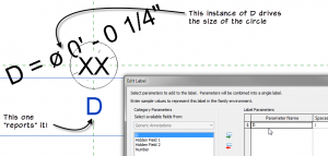
OK, so far so good. However, none of this is new. We have been able to do this for quite some time in Revit. Here is the part I just discovered. I wanted the circle to be parametric: I wanted to be able to flex the size of the circle. So I drew the circle, added a diameter dimension and then labeled the dimension with a family parameter that I called D.
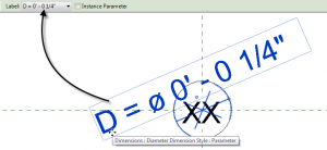
Now the really interesting part. Create another label (Create tab > Text panel > Label button).
Notice that you can add the dimension parameter D to the label! This basically means that the symbol will be able to tell you how big it is!!!
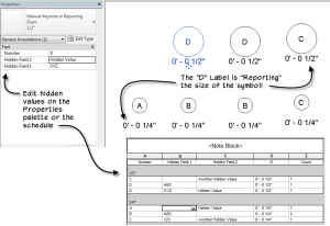
So D is now both a driving and a reporting parameter. Very cool! Let’s test it out. Save the family, load it into a project and place a few.
To edit the visible fields, you can click right on the symbol. To edit the invisible fields, use the Properties palette. Go ahead and create a Note Block schedule to list them all. Sort and group it how you like.
Annotation families are very useful. They are view-specific, adjust with the scale of the view and can be embedded in other families. All of the Revit tags and symbols are annotation families. But ONLY generic annotation families (Symbols) can report to Note Block schedules. They are useful for those cases where a true tag will not work, like certain types of finish annotation or other very specialized documentation.
I am not sure if this little “reporting parameter” behavior I stumbled on here will prove useful in a practical sense. But you can bet I will be exploring it further.
Have you found a practical use for this? Post in the comments, I’d love to hear about it. Thanks!
Here’s a file with a sample.
40 Responses to Generic Annotations in Revit
Comments are closed.
Categories
- Off Topic (1)
- Project Soane (2)
- BIM After Dark (Revit Kid) (2)
- Tips and Tricks (29)
- Oddities (5)
- Book News (23)
- Video Training News (7)
- Speaking Engagements (5)
- Renaissance Revit (12)
- Off Topic (8)
- Revit Concepts (1)
A speaker at RTC in Auckland shared this one with us last month. We put it in our Tips n Tricks session at the end of the conference. Nice write up Paul.
Hey Steve:
Thanks for the comment. Missed RTC in Auckland as you know. I’ll be in Vancouver next week. Great minds think alike I guess. Did they say if they had some practical uses for it? I am sure i’ll come up with something, but curious to know how others are using it.
Thanks.
One use case was “self reporting” mass families that displayed their area as you altered them.
Well that is a good one to try. If “real” work stops getting in the way of my experimenting that is… 🙂
Hi Paul,
Just purchased your Family Editor Video off Lynda.com – awesome video! Very useful and well explained. I also stumbled across this post which may come in handy. Just wondering, do you know of a way to change the line width of lines drawn in a Generic Annotation Family? I only seem to have the option of “Generic Annotations”. When I click on a line in my family, the contextual menu comes up and under Subcategory it displays only two options – ‘Generic Annotations’ and ‘Invisible lines’. I would like to make some lines in this family wider than others. I’ve tried adding new line styles by going to Manage/Settings/Additional Settings but noticed that Line Styles is greyed out so maybe it’s not possible. I’ve also tried copying an pasting different line styles from a sheet in a Revit project into the family but the lines automatically get converted to ‘Generic Annotations’. Any ideas?
Thanks for the comment and so glad you like the lynda.com videos.
To add line styles to a family, it is a little counter-intuitive. You actually go to Object Styles (Manage tab) and add a subcategory. Then you can set it to different settings and it will show when you draw lines.
Hope that helps.
Awesome Post! Super helpful. How do you adjust they scale of it once its loaded into your project like you mentioned?
Thanks again fro the post and help.
Hi Ken:
That is the beauty of Generic Annotations. They scale on their own as you change scale in the view. Build them their correct “printed size”. How big you want them when they print out. Then when you place them in a view they scale automatically based on the view’s scale setting.
Hi there,
Is there a way that you able to (in a family) add an additional type of reference plane. We are modelling some what we are calling Superfamilies (full rooms full of individual families) each individual item is constrained to a ref plane but there are as you can imagine lots an lots of them. It would be useful if we can add another type which could be colour coded differently so that they could be more easily identified. i.e one for type for fixed furniture, one for loose, one for services components etc, etc
Thanks in advance (even though i am sure the answer is no)
Hi Ben:
Short answer is as you already suspect: “no.” So sorry. This is HIGH on my wish list. I would love it if reference planes had types complete with different colors and line patterns…
What I usually do in complex families is vary the lengths of the reference planes. I am quite obsessive about this actually. I will size them in groups or pairs at the same lengths and then size others slightly longer or shorter. I also use Temporary/Hide Isolate constantly to help me make sense of everything.
Other things that I do are to make different dimension types. So while I you cannot color-code the reference planes, you CAN change the colors of the dimensions that flex them. So this can also help to visually group and make things manageable. Here is an example.
Finally, one other thing you could try is using lines. Both model lines and detail lines have the “Is Reference” parameter. They are not as powerful as reference planes, but depending on what you used them for, they may solve your current issue since they can have subcategories, colors and line patterns. Something to consider at any rate.
Final comment: be careful with “super” families. They can be very tempting, but often the amount of effort put into them both in creation and ongoing maintenance (not to mention file size and performance implications) can make them less valuable than at first hoped. This is not a “hard” rule of course. There are many successful super families. Just be sure that you are seeing both the forest and the trees as you develop them.
Good luck!
Paul.
Nice post. Have you been able to create an annotation symbol with shape handles? I’ve searched the web but found no help.
I am trying to create an annotation symbol that will function as a ‘frame’ around various information (i.e. sheet list, code analysis, project information, etc). I can have instance parameters to set the L and W but this would be easier for the average user to use Shape Handles to adjust the size.
Any suggestions?
Ian
Hi Ian:
Right you are. Having shape handles would be nice. Unfortunately I know of no way to do that with a generic annotation. As you noted, you can add parameters that show on the properties palette. In a detail module grid that I built recently for a client, we used a generic annotation and then I nested in an array that is controlled by instance parameters on the Properties palette to change the number of grids in both horizontal and vertical directions. It starts 2 x 2 and the user can increase this to whatever they need. Since it is a generic annotation, it adjusts to the scale automatically. So if your sheets are based on a standard grid module, this might be an acceptable solution for you. Here is an image of what it looks like:
Here is a link to the Revit family if you want to look at it.It uses nested filled regions on a subcategory so that they can be turned off and so you can snap to the edges.
Hope that helps.
Possibly a little late to the party here but have failed to find this solution online anywhere. If you want to have additional reference planes in your annotation symbol you can insert another annotation symbol as a group. Once inserted you simply explode and viola! you have reference planes that you can copy and dimension to and generate grip handles in the project.
One very large caveat to all of this. The Grip handles are affected by view scale so at 1:100 you get movement at a multiple of 100x which makes it near impossible to work with.
Interesting. I’ll have to give it a try.
I have a plate for medical gas which is wall hosted that I would like to have the annotation on the wall for the gas. I can get the symbol on the floor which is ok, but the client has asked for one on the wall so they can better understand the layout of the medical gases. When I view the gas outlet family in elevation the symbol button is grayed out. Your assistance solving the issue is greatly appreciated
There are “hacky” ways to embed text and annotation directly in 3D families, but really what you are supposed to do is tag them. I would recommend making a tag for the gas item and then you can add this to any view you like in the project: elevation, section, even 3D if you lock the view first. This will work much better than trying to embed it into the family.
I have done the above by adding model text to the elevation – for the very reason described above (showing different medical gases). Then created family types in that family for O,V,A set on visibility parameters. From our use, we have not had a need for this text to disappear, so didn’t bother with any other visibility settings.
Hi David:
Thanks for the comment. I agree, model text is another good option. It is part of the model, so as you say, in some applications visibility can be an issue. But there are ways to control it. Also, since it is part of the model, it will have an absolute size and will not adjust with the view scale. It sounds like that works well in your use case, but in some cases, it may not be as successful.
Margaret,
In the Family Category and Parameters you can find a parameter “Maintain Annotation Orientation”. This will help you with showing the nested symbol family in the project plan view. Just put the symbol family in a plan view of the original face-based family. This applies to: Communication Devices, Data Devices, Electrical Fixtures, Fire Alarm Devices, Lighting Devices, Nurse Call Devices, Security Devices, Sprinkler and Telephone Devices.
Never too late…
hey Paul Nice to know you, i like your tutorial video
i want to ask something,
i still don’t understand with the scale, i use revit 2016 student version,
as default the scale in revit is 1 : 100 , everytime i change it into 1:1 ( as a real time scale) suddenly the text of dimension is changed into microscopic letter. also i loose my elevation mark, what is the solution?
i am metric user, i need to draw in real time scale 1:1
thank you
Hello:
Revit incorporates scale in exactly the same way that you would do in Architectural drafting. Unless you are drawing something very small, you must work in scale to have things fit on sheets for printing. It is possible to work at 1:1, but not really desirable unless you are building something small like perhaps a very small piece of furniture or something similar. Text always adjust to the scale, but the model elements are always full size. So if you are worried that your walls and other model elements will not be the correct size if you don’t work at 1:1, then don’t worry about that. Model elements in Revit are ALWAYS drawn full (life) size. Annotation scales to the printing scale. So choose a scale that is appropriate for the size you intend to print and everything else will take care of itself.
Hope that helps.
Paul,
Thanks for this post, great info. Love your Lynda tutorials as well. Can you tell me though, is there a way for a generic annotation to be able to report its location on a sheet? I’m trying to use a generic annotation to note changes from a client that don’t meet the standard for a revision log. I created a generic annotation family and have a number and text field that I can then schedule via your method above. Would be perfect if I could place this schedule on the cover sheet and add a field that shows a view reference. Have been working around this with a manual label in the annotation family.
-Ben
Hi Ben:
The simple answer is that I don’t think so. However, I am always up for a new challenge. If you want to send me what you have currently, I can take a look and see if it can be improved. Drop me a note using the contact form here on the site and I will try to get back to you soon.
Thanks.
paul
Hi Paul,
We use this method for our MEP work notes using various symbols, like hexagons, circles, etc. Is there a way to place the symbol in the actual note block, so that the numbered list of notes each has a hexagon around the note number?
Right now, we’re adding the symbol to each one by eye-balling it. Trouble is, when the notes change, the symbols need to be re-positioned.
Thank you
Hello:
You can incorporate images in schedules. They only work for Type properties in my experience. They do show up on Properties palette for instances, but I have had no luck making that work. Trouble is, you cannot combine an image property with another property. So the image would just be a blank hexagon or blank circle. Not great, but might get you closer to what you need.
Thank you for the answer, Paul!
Hi Paul,
i was searching on topic of “annotation symbol in elevation views” we have a 2d valve family which should show in plan and elevation and it should change as per view scale both in plan and in elevation view. you mentioned above some hack way’s. can you please explain so may be we can try these hack way’s.
Hello, I cannot recall where I mentioned any hacks for this. Typically, annotation symbols only insert in the plan views in the family editor. They can be inserted in any view in the project, so this is particularly frustrating if you want to achieve what you mentioned. I have tried embedding annotation into nested detail items. This sort of works, but I could not get them to show up when bringing that family into the project. So, ultimately, this may be something that has no solution currently.
Hi Paul I want to know the basic difference between templates of generic annotation and detail items or any other detail related templates? Why are there these many types of templates only related to detailing?
Hello:
Both generic annotations and detail items are “view-specific” meaning they only appear in the view they are created in.
The Generic Annotation template is for symbols and they will automatically adjust scale when the view scale changes.
Detail Item templates create 2D families that represent full-scale (life sized) items. They do not adjust scale.
Hope that helps.
paul
Hi Paul, I red your RAC2016 book chapter5, looked in every single post I’ve found with google, etc. but cannot find a way to link my “OOTB hard coded” project info parameters to the custom shared parameters I put in my titleblock labels.
My aim is to make a parametric company titleblock template which can vary in its content depending on the project it applies to : 3 languages, Mandatory pave with sheet titles and numbers, typical optional stakeholder pave to repeat depending on how many are involved, optional approval pave & revision table. All enclosed in a parametric frame working for all ISO sheet sizes.
So…. because we cannot parametrize the positon of labels, I’ve created some GA label families, nested inside GA pave families, nested inside my Titleblock Family, all sharing the same shared parameters…. and now I’m stuck with it ! Shared parameters of the families cannot be linked to the (ootb or custom) sheet or project info project parameters ! aargh !
Have you ever test that ? Do you have any hints for me ?
Hello:
I am not sure what you mean by “pave”
I am not sure if you can use nested GA families in the titleblock. I have never tried that for labels, only for things like North Arrows and such. But why not just use visibility parameters for labels to turn them on and off?
Hi Paul, I have been nesting generic annotation texts in several kitchen machinery families that I am currently doing for a project. Do you know if there is any way to hide these generic annotations from view for instance starting at scales coarser than 1:50? Same way like the section symbols in plan views hide at scales coarser than 1:100 (or what ever one chooses). Thanks 🙂
Not really. You cannot hide generic annotations at certain scales. They will adjust to scale, but they show all the time. If they are not nested in model families, this is not a problem as you simply add them only to views whose scale is set at ones where you want them to show. But since you are nesting them in model families, you will have to control the visibility in some other way. You can use checkbox parameters (Yes/No) and toggle this off. But unfortunately this will not be per view or per scale but global. The only other thing I can think of is to try using Course, Medium and Fine. So select the Nested generic annotation and click on Visibility Graphics. Uncheck Course. Then, in views of small scales, set them to Course and the symbols will hopefully disappear. (I say hopefully, because I have not tried this myself yet). Good luck.
Hi Paul,
Thank you for all of your interesting topics, I have a question regarding annotations. Is there a way to show text in a family elevations/sections when loading them back to the project? Other than having to use model text?
Thank you very much.
You can nest a generic annotation (with text or labels in it) into another family. This will show through in parallel views. I have done this successfully in plan views. I am not 100% sure about sections and elevations, but it should work.
Did you ever find a way to show the Sheet a Generic Annotation is on?
There is probably a way to do this in Dynamo. I’ll add it to my list…
Cool, is there any way to scale or change the text size as well?
You can make a different Text Type. But otherwise no. Text is “by design” sized to a fixed print size.